Monday, May 30, 2016

Vale Merv Inions

Mervyn Inions
It is with great sadness that the S class has lost another one of its long time friends, that of Merv Inions. Not many would know Merv, but without him the road to restoring S549 in the 90's would have been that much more difficult.

Merv was a boilermaker who started with the WAGR in the 1950's and retired when the workshops closed in 1994. In the later years after steam died, he looked after the workshops boilers which included the four ASG locomotive boilers and the workshops air receivers also assisting the boiler inspector with annual inspections of these vessels also.

He also helped with the various preservation groups in the state and his score card goes something like this, but not limited to;
  • Worked on the two G class overhauls in the 70's
  • He returned the boiler of DD592 to operating condition in the 80's
  • He assisted with re-tubing a couple of Hotham Valleys W class boilers
  • Assisted Bennett Brook Railway with various projects including work on the Mallet boiler and another locomotive possibly the Perry, Betty Thompson
So where does he fit into S549's story.?

Once Merv found out about the work on 549, he assisted with the loan of tools and equipment to get the boiler up to spec. Most of all, he allowed access to his wealth of knowledge which was priceless, he unselfishly trained and passed on his skills to me (whilst assisting him on the projects listed above) of which I have now been passed onto others with the current S class re-tubing project.

He was also responsible for restoring various parts of her (at the Midland Workshops) in the early 90's including various boiler fittings and the spark arrestor components prior to them being installed into the smokebox.

I last saw Merv around 6 months ago when I went to see him to obtain advice on the selection of new tube expanding equipment and beading tools to be used on the recent re-tubing of 549's boiler. Like always, very willing to help where and when he can.

He will be sadly missed.


Saturday, April 9, 2016

Project Report - 9 April 2016

A fair bit has been going on with the S class since the last update.


Boiler Preparation For A Hydrostatic Test

Now that the tubes have been installed, the boiler needs to hydrostatically tested, our friends at Wikipedia explains;

A hydrostatic test is a way in which pressure vessels such as pipelines, plumbing, gas cylinders, boilers and fuel tanks can be tested for strength and leaks. The test involves filling the vessel or pipe system with a liquid, usually water, which may be dyed to aid in visual leak detection, and pressurization of the vessel to the specified test pressure. Hydrostatic testing is the most common method employed for testing pipes and pressure vessels. Using this test helps maintain safety standards and durability of a vessel over time.

So the next step was to seal (plug up) all the other holes in the boiler so the vessel could be pressurized. The holes were in the form of washout plug holes and boiler fitting mounts such as safety valves and clack valves.

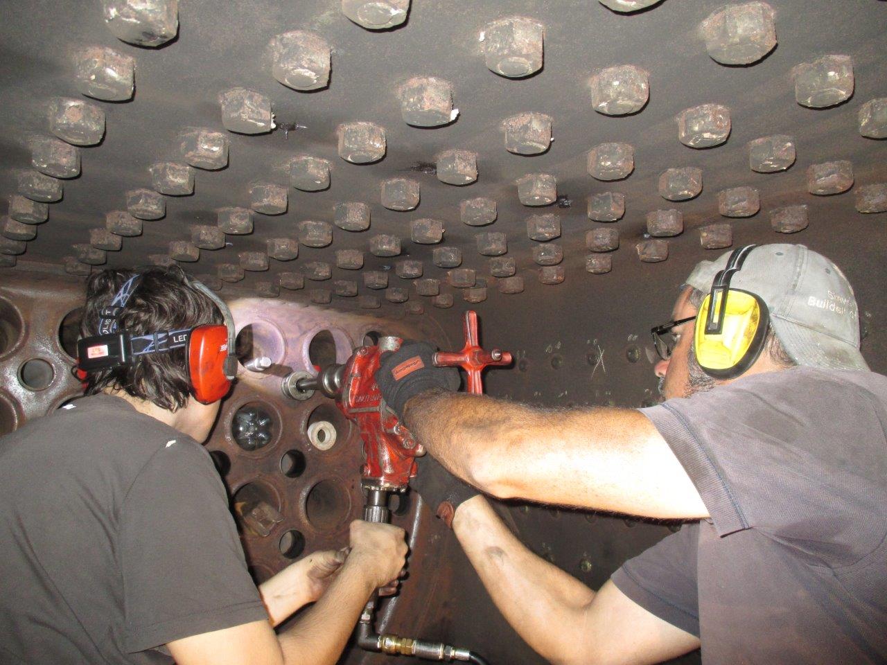
The washout plug holes are a tapered threaded hole of which a bronze (Leaded Gunmetal) tapered plug is fitted. Some of the threaded holes required cleaning up to ensure a good seal is formed when the plug is fitted, to do this washout plug taps were borrowed from Bennett Brook Railway and Ian Willis, we are extremely grateful for the loan of these. Once the threads were restored, the plugs were sorted for the correct size and refitted.
WAGR drawing of a washout plug

Washout plug tap
For the boiler mounts, special blanking plates were required. Each mount was measured, drawn on AutoCAD, cardboard templates produced to test to ensure the dimensions were correct and then subcontracted out for manufacture. The blanking plates were manufactured by Pressform using a CNC (Computer Numerical Control) mill to ensure accuracy. Unfortunately on a couple of mounts the pitch between studs varied slightly and the plates for these required some fine tuning by Kirk with a KOHF (Kirk Operated Hand File). A gasket was also required between the blanking plates and the mounts, John manufactured these out of rubber insertion. The plates and gaskets were then fitted and the securing nuts and washers tightened up.

Blanking plates fitted to the safety and clack valve mounts
As the boiler required to be pressurised a pump was necessary to carry out this task, luckily enough there was one in storage. John took on the task of getting the pump operating; new fittings and pump to boiler hose acquired to ensure there were no leaks for the test.

The last task was to replace the fusible plug leads, these are a safety device in the event of the water level in the boiler dropping below the firebox crown, the leads melt and the pip drops out allowing the steam to put the fire out minimizing warping the firebox shell and other damage to the boiler.

Fusible plug assembly as fitted 

Fusible plug mounting nut with conical plug removed 
There are four fusible plugs fitted to the S class locomotives, roughly one in each corner of the firebox. They consist of a mounting nut, conical plug with the fusible lead and a pip (tapered brass plug) fitted.

The conical plugs were removed and the leads/pip (gently) punched out, the lead is then gently knocked with a hammer to stretch/deform it, allowing the lead to slip off the pip. All parts were then cleaned up to remove any contaminants. A replacement lead was then slipped onto the pip and then fitted into conical plug and then firmly knocked into position to seal. The conical plugs were then refitted into the mounting plugs.

Fusible plug assembly,
Left - water side - showing the pip & lead
Right - fire side showing removal socket

Fusible plug assembly
Left to Right - Conical Plug, Pip, Fusible Lead
Rear - Completed Assembly
Upon completing the sealing up of the boiler, the plan was to carry out a trial a low pressure hydro test to ensure any slight leaks could be rectified prior to calling the boiler inspector. We did this and unfortunately the studs that were fitted in the steam dome that hold the dryer and steam pipe in position leaked. The studs were removed by Dom and with assistance from John Wearmouth drawings were located of the originals. Dom arranged to have replacement studs manufactured by Verriers Engineering in Bassendean who generously offered to provide at no cost, thanks Verriers.  www.verriersengineering.com.au The new studs were then fitted by Dom and the blanking plates reinstalled.

A trial low pressure hydro test was then carried out and the studs sealed this time. The tubes were inspected and only one weaped slightly at the smokebox end. The pressure was dropped and the tube was lightly re-expanded, finally we're ready for Doug (Boiler Inspector) to run his eye over her. Doug was contacted and arrangements were made to carry out the hydrostatic test on Saturday 9 April.

Saturday, 9 April - The team started early to ensure the area was set-up, Doug arrive around 10am and the tap was turned on to allow water off the mains pressurize the boiler, this took the boiler up to around 75psi in pressure. Doug then started his rounds, in the firebox, in the smokebox, along the sides and no leaks were found. OK let's start the pump and get the pressure up to operating pressure of 190psi which took around half an hour, still no major concerns. The pump was again turned on and the pressure increased to a higher pressure above the normal operating pressure (safety margin) to ensure the vessel would be sound in its normal operating condition. The pump was turned off and Doug again carried out his rounds.

Finally, all good was given by Doug and the pressure was slowly released. Now for the next step, put her back together again.

Other Works in Parallel


Whilst the work in preparing the boiler was going on, other work was being carried out in parallel.

Boiler Mount Gaskets - Following the Hydro test, the locomotive and all its fittings need to be reassembled, the fittings will need a gasket suitable for steam and as John had already made the rubber gaskets for the hydro test, he went on to source the steam gaskets also. Several companies were contacted and their products reviewed against our requirements, Novus Sealing Pty Ltd was selected as the supplier with their product Novus 30. Brett Mohen, Novus's Technical Sales Representative was extremely helpful as he had first hand experience in steam requirements as he is also a volunteer at the Hotham Valley Railway and knew exactly what we needed, thanks Brett.

Boiler Surface Preparation - Twenty five plus years ago, the boiler was sitting on sitting on specially built stands off the engine, the decision was made to sand blast the exterior surfaces and paint in a zinc rich primer. It actually held up quite well in some area's but not in others over the years since it was initially done.

We didn't have the luxury of sand blasting it this time due to concerns in getting the abrasive sand into the operating equipment of the locomotive, not worth the risk. John and Alec researched a rust converter and top coat for the boiler and two products were selected, Fertan Rust Converter and a high temperature zinc rich primer.

Firebox with Fertan applied

Firebox with the High Temp Zinc Rich Primer applied
John and Andrew then proceeded to remove any loose scale and surface rust and coat the surface with the converter, after the recommended period for the converter to do its work, the top coat was then applied. Andrew had the task of doing the area underneath the boiler barrel, between the frames, nice and squeezy, well done Andrew. The boiler where completed to date looks as good as new and should see it protect the boiler for the next twenty five plus years, well done guys.

Painted Boiler - Looks like new
Steam Regulator Overhaul - John Wearmouth has taken on the task of overhauling the steam regulator valve. Basically this valve is operated by the driver and when opened by him, steam is delivered to the cylinders making the engine go forward or backwards, a very important valve. John's father had previously overhauled the valve as part of the original restoration of the locomotive 20+ years ago. The parts have now been cleaned up and repair requirements noted, some new components will need to be manufactured.

Crinoline Bar Replacement - Crinoline bars are what support the exterior cladding or clothing away from the boiler shell, initially it was thought that the 70 year old items would make do for another 10 years, we were kidding ourselves. The original bars had corroded to the point that in sections were only a couple on millimeters thick, they were loose on their brackets due to the thinning of material and the threaded holes used for bolting the cladding to were void of any thread at all. Time for replacements. The existing bars were then removed by John, Greg and Kirk however the mounting brackets now require drilling out and re-tapping, Dom is in the process of carrying out this work.

John and Greg removing the Cowling Crinoline Bars

Kirk marks the Crinoline bar for tracability

A busy few months indeed, stay tuned for more updates shortly. If you would like to be informed when there is an update, simply follow by email located on the right hand side of this page. Thanks for your ongoing interest, we are looking forward to seeing her in steam once again.

Major Milestone Acheived - 9 April 2016

                    MAJOR MILESTONE REACHED

Hydrostatic Boiler Pressure at Normal Operating Point
Today we passed a major milestone with the boiler being hydrostatically tested in the presence of the boiler inspector. The final pressure was above what the locomotive would normally operate at being 190psi, (i.e. a safety margin allowed) and the end result was that no major concerns were noted.

I would like to thank all those that have been involved on the project to date, without you we would not be where we are today. The fun now begins in putting it all back together again.!!


I will update you shortly of what we were up to between the last update and today, keep checking.

Saturday, January 30, 2016

Project Update - 30 January 2016

With the tube expanding out the way, the beading of the tube ends in the firebox was required next.

Beading of the tube is a metal forming process in which the ends of the tubes are rolled over onto the tubeplate to further seal or caulk the expanded joint.

It is performed by using a beading tool and a small pneumatic hammer (Caulking Gun). Slowly but surely the beading tool is knocked by the piston in the gun which in turn knocks the end of the tube curling it towards the tube plate.

Caulking Gun
Beading Tool

Beading of a tube.


Beaded Tube
The beading of the tubes took several days to complete, once again the team all contributed to the task with excellent results.
John in action
Greg checking to see how the bead is going closing up onto the tube plate
Kirk beading one of the top row, your arms soon let you know your working up there..!!

During the boiler tube replacement, members of the Bennett Brook Railway at Whiteman Park were invited to visit Bassendean to observe the process and give it a go on the training module as they also have boiler tube replacement on their future maintenance programme. Brayden Hesford and Michael Watson have since visited and I am sure taken away an understanding of what it involves.   
Brayden expanding and flaring a tube at the firebox end of the module.
Michael expanding a tube at the smokebox end of the module.

BEADING COMPLETE


We also had the opportunity today to remove the sandbox as working around it has been a pain in the (well you know where) since the start of the project. With the aid of the recently acquired forklift and its competent operator Dom, the job of re-cladding the barrel will be so much easier. The steam dome cover was also lifted into position in readiness for the next step, the hydro.
Sandbox, down you come.
Well not really down at all, it ended up on the top of the water space
at the rear of the tender out of harms way.

So what's the next step..? The hydrostatic test, so stay tuned..

Tuesday, January 5, 2016

Project Update - 5 January 2016

With the training on the module out of the way, work commenced on installing the tubes in 549's boiler. Fortunately (or unfortunately depending on your view) most of the team were on leave so this enabled mid week work as well as the normal Saturdays.

Over six work days the team expanded all 93 tubes, slow but steady, no point rushing the job and paying for it later.

We would do them in batches, firstly the tube plate holes required polishing to remove any surface rust followed by removing any contaminants on the external surface of the tubes, this took a fair bit of time in itself. In regards to the expanding, we commenced in the firebox end, this would take the longest time due to measuring the stick out, measuring the tube wall reduction, ensuring the tube doesn't flare immaturely and the shear awkwardness of being in the firebox. This was later followed by the smokebox end.

It was hard work due to the awkwardness of the confined spaces not to mention some bloody hot days thrown in.

All of the team contributed to getting the work done and without the commitment of each of them at different stages over the six days, the work would not have been completed in the professional format that it was. Thanks to John, Kirk, Greg, Andrew, Alex, Jayden & Josh.

Some snapshots of the work in progress.

Alex and Kirk in action
Kirk measuring tube stick out
Onto the top row, Jayden and Kirk
John at the controls, assisted by Jayden
Job complete, all tubes expanded - firebox end
Job complete, all tubes expanded - smokebox end
Next task - Tube beading in the firebox.

Sunday, December 13, 2015

Project Update - 12 December 2015


The plan for today is to simulate on the training module what we will be doing on 549's boiler in regards to the installation of the tubes.


The day started quite early and the initial events went a bit like this;
  • 8.30am at Bunnings to pick up a 30M air hose. The compressor is diesel powered and generates a lot of noise and fumes, we want it as far away as possible from the work area.
  • 9am at the museum, move the Sherman Tank (Compressor) from next to S549 to outside of the workshop.
  • 9.30am - Dom kindly provided the hose fittings and attachments and also provided the service of fitting them to the hose, compressor and tooling. Thanks Dom.
  • 10am - The team assembles on site eager to get into it. The module is located in a workable area and the all the tooling is assembled and laid out.
The first thing that we needed to do was to calculate the amount of tube side wall reduction or crush on the tube we needed to achieve to ensure they do not leak under pressure. The tube in its current state is loose within the tube plate, we need to workout the gap between both, then work out what the tube inside diameter will be if there is no gap, followed by if we were to further crush the tube against the tube plate.


There is a simple calculation formulae that will give us the answer, it goes like this: (I am going to use actual measurements taken for an S class).


Step 1, work out the clearance between the tube and the tube plate,
  1. Measure the tube plate hole                                           58.625mm
  2. Measure the outer diameter of the tube                         57.150mm
  3. The clearance is determined by subtracting 2 from 1      1.475mm
Step 2, what would the inside diameter of the tube be if there was no clearance between the tube and the tube plate.
  1. Measure the inside diameter of the tube                       50.840mm
  2. Add the clearance determined in step 1                          1.475mm
  3. Inside diameter at metal to metal (no compression)     52.315mm
Step 3, the required wall reduction or additional crush needs to be added to the inside diameter, for steel to steel tubes it is 7%.
  1. Determine the wall thicknesses of the tube by subtracting the inside diameter from the outside diameter, step 2.1 from step 1.2. (57.150mm - 50.840mm) 6.31mm                                     
  2. Calculate 7% of the wall thickness which will determine how much we need to reduce the walls of the tube.                                                               0.4417mm 
  3. Add the 7% to the inside diameter at metal to metal from step 2.3, this then will give the expanded tube inner diameter.  52.315mm + 0.4417mm = 52.7567mm
Kirk and Josh calculating the required wall reduction
Now that the arithmetic lesson was over, we needed to get our hands dirty. The first job was to ensure the rolling surfaces of the tubes were clean from rust and scale. This reduces damage and ensures longer life for the expanders.
Josh cleaning the insides of the tubes prior to expanding
We decided to experiment a bit further with the tube projection just to ensure we have got it right, this time we chose the measurements of 5.5, 6, 6.5 and 7mm. We clamped and wedged the tube at the smokebox end of the first tune and ensured the projection at the fire box end was 5.5mm, we then expanded and flared the firebox end. We then progressed through the next three tubes ensuring the projection was correct for each. Following the expansion process, each of the tubes inside diameter were measured to ensure we were achieving the required wall reduction.
Expanded and flared tube - Fire box end

We then went onto the smoke box end and expanded these also, again measuring the inside diameter to ensure we were achieving the required wall reduction.
Signs of a happy team. Josh and Greg expanding the smokebox ends of the tubes
The four tubes were then beaded, demonstrating the process to Josh, Greg and Kirk of how its done, don't worry your turn will come. From this, the ideal projection was found to be 6.5mm.

Greg, Kirk and Josh then took over and expanded and flared another six tubes, the only way you'll learn is to give it a go for yourself. The three amigo's all took turns at the controls, all the tubes were expanded beautifully with Josh taking the gold medal in expanding the perfect tube at 52.7567mm inside diameter, amazing.

And now for what everyone has been waiting for, the beading. Under the watchful eye of the boilermaker, each of the team took turns in expanding a tube each, I must say for first timers they all did exceptionally well (maybe too well, might put me out of work..!!).
Greg giving his first tube a go at beading
Kirk's turn - Kirk is currently doing an apprenticeship as a boilermaker at ANI.
Not too many apprentice boilermakers pick up these skills anymore. 
The team today did extremely well today, eager to learn and as a end result new skills being learnt. Just goes to show, anything is achievable with the right attitude and enthusiasm.
The end result of the training session.
Note: the four tubes that the projection were trialed are the second row up with the
smallest projection (5.5mm) starting from the left, the 6.5mm one is the third from the left. 
Well that's it for this week, we will be commencing on the installation of the tubes on S549 this weekend - stay tuned.

Sunday, December 6, 2015

5 December 2015 - Project Update


On Saturday the 5th of December we played around with the training module once again, the plan was to try out the pneumatic tooling, the tube set-up and expanding/beading techniques.

But firstly, following the initial trial on the training module, a number of items were identified to be obtained prior to giving the real test case a go; no use going full steam ahead if we are stuffing around with 1/2 of the required equipment. The list went like this;
  • 3/4 drive to Morse adaptor insert; the new tube rolling equipment mandrels are 3/4 drive and you guessed it, we had every size but..! That's where we get local industry involved and have components manufactured to our specifications. Pressform Engineering manufactured two new adaptors and they work a treat.
  • Corking gun - Loaned from a former WAGR boilermaker that happened to still have one in his cupboard, its not what you know but who you know.
  • Compressor - When we did the first trial, the volume of air that was available from the small compressor was good but for about 30 seconds, to install the tubes on the S would have taken more time than what's available in our lifetime anyway...! The word went out and Boulder Loopline came to the rescue with their compressor, thankyou.
One of the tasks we wanted to confirm today was the amount of tube projection from the firebox tube plate. I was always told that it should be between 3/16 and 1/4 of an inch but I wanted to confirm a length prior to installing all the tubes into the boiler. This is very important because too little projection runs the risk of damage to the tube plate when beading the tube, too much and there is the risk of poor beading due to excess material.
Drawing showing tube projection and flaring
So we set three tubes up, the first at 4.7625mm (3/16"), the next at 5.5mm and the last at 6.35mm (1/4") and with the use of the pneumatic motor and expanders we expanded and flared all three.We expanded and flared the three tubes at the firebox end first ensuring the projection was what we wanted, we then moved to the smoke box end and expanded the tubes at this end also.


Now for the beading. We purchased several beading tools when we ordered the expanders, we however found that they required a fair bit of shaping as initially they wanted to dig into the tube and cause damage, this took several goes to get right.
Typical beading tool
The Three Amigo's, following beading of the ends.
Note: damage to tube plate on the left and centre tubes due to insufficient
tube projection (4.76 and 5.5mm respectively).
The tube on the right was set at 6.35mm stick-out and beaded nicely.
Close up of the right (good) tube.
Drawing of expanded and beaded tube
We persevered with the small compressor for these three tube which added to the difficulty but never the less we achieved a fair bit today.

The plan for next week is to finalise our techniques and to train (give a go) the members of the team so we all know what is expected on the boiler.