The plan for today is to simulate on the training module what we will be doing on 549's boiler in regards to the installation of the tubes.
The day started quite early and the initial events went a bit like this;
- 8.30am at Bunnings to pick up a 30M air hose. The compressor is diesel powered and generates a lot of noise and fumes, we want it as far away as possible from the work area.
- 9am at the museum, move the Sherman Tank (Compressor) from next to S549 to outside of the workshop.
- 9.30am - Dom kindly provided the hose fittings and attachments and also provided the service of fitting them to the hose, compressor and tooling. Thanks Dom.
- 10am - The team assembles on site eager to get into it. The module is located in a workable area and the all the tooling is assembled and laid out.
There is a simple calculation formulae that will give us the answer, it goes like this: (I am going to use actual measurements taken for an S class).
Step 1, work out the clearance between the tube and the tube plate,
- Measure the tube plate hole 58.625mm
- Measure the outer diameter of the tube 57.150mm
- The clearance is determined by subtracting 2 from 1 1.475mm
Step 2, what would the inside diameter of the tube be if there was no clearance between the tube and the tube plate.
- Measure the inside diameter of the tube 50.840mm
- Add the clearance determined in step 1 1.475mm
- Inside diameter at metal to metal (no compression) 52.315mm
Step 3, the required wall reduction or additional crush needs to be added to the inside diameter, for steel to steel tubes it is 7%.
- Determine the wall thicknesses of the tube by subtracting the inside diameter from the outside diameter, step 2.1 from step 1.2. (57.150mm - 50.840mm) 6.31mm
- Calculate 7% of the wall thickness which will determine how much we need to reduce the walls of the tube. 0.4417mm
- Add the 7% to the inside diameter at metal to metal from step 2.3, this then will give the expanded tube inner diameter. 52.315mm + 0.4417mm = 52.7567mm
 |
| Kirk and Josh calculating the required wall reduction |
Now that the arithmetic lesson was over, we needed to get our hands dirty. The first job was to ensure the rolling surfaces of the tubes were clean from rust and scale. This reduces damage and ensures longer life for the expanders.
 |
| Josh cleaning the insides of the tubes prior to expanding |
We decided to experiment a bit further with the tube projection just to ensure we have got it right, this time we chose the measurements of 5.5, 6, 6.5 and 7mm. We clamped and wedged the tube at the smokebox end of the first tune and ensured the projection at the fire box end was 5.5mm, we then expanded and flared the firebox end. We then progressed through the next three tubes ensuring the projection was correct for each. Following the expansion process, each of the tubes inside diameter were measured to ensure we were achieving the required wall reduction.
 |
| Expanded and flared tube - Fire box end |
We then went onto the smoke box end and expanded these also, again measuring the inside diameter to ensure we were achieving the required wall reduction.
 |
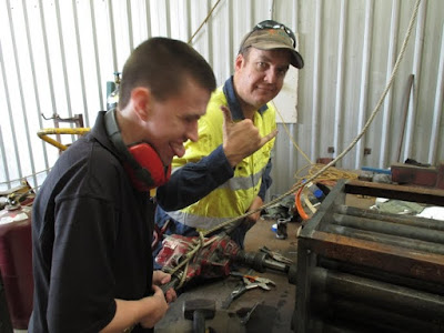
| Signs of a happy team. Josh and Greg expanding the smokebox ends of the tubes |
The four tubes were then beaded, demonstrating the process to Josh, Greg and Kirk of how its done, don't worry your turn will come. From this, the ideal projection was found to be 6.5mm.
Greg, Kirk and Josh then took over and expanded and flared another six tubes, the only way you'll learn is to give it a go for yourself. The three amigo's all took turns at the controls, all the tubes were expanded beautifully with Josh taking the gold medal in expanding the perfect tube at 52.7567mm inside diameter, amazing.
And now for what everyone has been waiting for, the beading. Under the watchful eye of the boilermaker, each of the team took turns in expanding a tube each, I must say for first timers they all did exceptionally well (maybe too well, might put me out of work..!!).
 |
| Greg giving his first tube a go at beading |
 |
| Kirk's turn - Kirk is currently doing an apprenticeship as a boilermaker at ANI. Not too many apprentice boilermakers pick up these skills anymore. |
The team today did extremely well today, eager to learn and as a end result new skills being learnt. Just goes to show, anything is achievable with the right attitude and enthusiasm.
Well that's it for this week, we will be commencing on the installation of the tubes on S549 this weekend - stay tuned.


